 |
Application: | Telecom and wide variety of electronic equipment (up grade from 60V FRX). |
| Product Features: | Low hold current, Solid state, Radial leaded product ideal for up to 90V | |
| Operation Current: | 100mA~3.75A | |
| Maximum Voltage: | Up to 90V | |
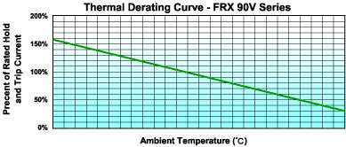
| Temperature Range: | -40°C to 85°C | |
| Agency Recognition: | UL (E211981) C-UL (E211981) |
| Part Number |
Hold Current |
Trip Current |
Max.Time to Trip |
Maximum Current |
Rated Voltage |
Typical Power |
Resistance Tolerance | |
| RMIN | R1MAX | |||||||
| IH, A | IT, A | at 5xIH | IMAX, A | VMAX,Vdc | Pd, W | ohms | ohms | |
| FRX010-90 | 0.10 | 0.20 | 4.0 | 40 | 72/90 | 0.38 | 2.50 | 7.50 |
| FRX015-90 | 0.15 | 0.35 | 10 | 40 | 72/90 | 0.70 | 2.40 | 7.00 |
| FRX017-90 | 0.17 | 0.34 | 3.0 | 40 | 72/90 | 0.48 | 2.00 | 5.00 |
| FRX020-90 | 0.20 | 0.40 | 2.2 | 40 | 72/90 | 0.41 | 1.83 | 4.40 |
| FRX025-90 | 0.25 | 0.50 | 2.5 | 40 | 72/90 | 0.45 | 1.25 | 3.00 |
| FRX030-90 | 0.30 | 0.60 | 3.0 | 40 | 72/90 | 0.49 | 0.88 | 2.10 |
| FRX035-90 | 0.35 | 0.75 | 10.0 | 40 | 72/90 | 1.30 | 0.70 | 2.50 |
| FRX040-90 | 0.40 | 0.80 | 3.8 | 40 | 72/90 | 0.56 | 0.55 | 1.29 |
| FRX050-90 | 0.50 | 1.00 | 4.0 | 40 | 72/90 | 0.77 | 0.50 | 1.17 |
| FRX055-90 | 0.55 | 1.20 | 10.0 | 40 | 72/90 | 1.50 | 0.40 | 1.50 |
| FRX065-90 | 0.65 | 1.30 | 5.3 | 40 | 72/90 | 0.88 | 0.31 | 0.72 |
| FRX075-90 | 0.75 | 1.50 | 6.3 | 40 | 72/90 | 0.92 | 0.25 | 0.60 |
| FRX090-90 | 0.90 | 1.80 | 7.2 | 40 | 72/90 | 0.99 | 0.20 | 0.47 |
| FRX110-90 | 1.10 | 2.20 | 8.2 | 40 | 72/90 | 1.50 | 0.15 | 0.38 |
| FRX135-90 | 1.35 | 2.70 | 9.6 | 40 | 72/90 | 1.70 | 0.12 | 0.30 |
| FRX160-90 | 1.60 | 3.20 | 11.4 | 40 | 72/90 | 1.90 | 0.09 | 0.22 |
| FRX185-90 | 1.85 | 3.70 | 12.6 | 40 | 72/90 | 2.10 | 0.08 | 0.19 |
| FRX250-90 | 2.5 | 5.00 | 15.6 | 40 | 72/90 | 2.50 | 0.05 | 0.13 |
| FRX300-90 | 3.00 | 6.00 | 19.8 | 40 | 72/90 | 2.80 | 0.04 | 0.10 |
| FRX375-90 | 3.75 | 7.50 | 24.0 | 40 | 72/90 | 3.20 | 0.03 | 0.08 |
IT=Trip current-minimum current at which the device will always trip at 23°C still air.
V MAX=Maximum voltage device can withstand without damage at its rated current.
I MAX= Maximum fault current device can withstand without damage at rated voltage (V max).
Pd=Typical power dissipated from device when in the tripped state in 23°C still air environment.
RMIN=Minimum device resistance at 23°C.
R1MAX=Maximum device resistance at 23°C, 1 hour after tripping .
Physical specifications:
Lead material: FRX010~FRX090 Tin plated copper, 24 AWG. FRX110~FRX375 Tin plated copper, 20 AWG.
Soldering characteristics: MIL-STD-202, Method 208E.
Insulating coating:Flame retardant epoxy, meet UL-94V-0 requirement.
 |
 | |||||||||||||||||||||||||||||||||||||||||||||||||||||||||||||||||||||||||||||||||||||||||||||||||||||||||||||||||||||||||||||||||||||||||||||||||||||||||
| FRX 010-90 ~ FRX 090-90 Lead Size :24AWG, Ø 0.51 mm Diameter |
FRX 110-90 ~ FRX 375-90 Lead Size : 20AWG, Ø 0.81 mm Diameter | |||||||||||||||||||||||||||||||||||||||||||||||||||||||||||||||||||||||||||||||||||||||||||||||||||||||||||||||||||||||||||||||||||||||||||||||||||||||||
| ||||||||||||||||||||||||||||||||||||||||||||||||||||||||||||||||||||||||||||||||||||||||||||||||||||||||||||||||||||||||||||||||||||||||||||||||||||||||||
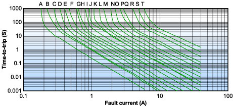 | |||
| A = FRX010-90 | B = FRX015-90 | C = FRX017-90 | D = FRX020-90 |
| E = FRX025-90 | F = FRX030-90 | G = FRX035-90 | H = FRX040-90 |
| I = FRX050-90 | J = FRX055-90 | K= FRX065-90 | L = FRX070-90 |
| M= FRX090-90 | N = FRX110-90 | O = FRX135-90 | P = FRX160-90 |
| Q = FRX185-90 | R= FRX250-90 | S = FRX300-90 | T = FRX375-90 |
![]()
|
|
| Warning: |
|
|
|
All the specifications are subject to change without previous notice.